Suspension Kinematics Calculation: A Practical Guide to Tools, Methods, and Validation
Accurate suspension kinematics calculation is the foundation of predictable handling, optimal tire contact, and vehicle stability. This guide provides a practical, engineering-focused approach to calculating kinematics, emphasizing tool selection, model limitations, and validation with physical testing.
Key Kinematic Parameters: What You Need to Calculate and Why
Before diving into calculations, you must understand the parameters that define suspension behavior. These are the building blocks of vehicle dynamics.
Roll Center
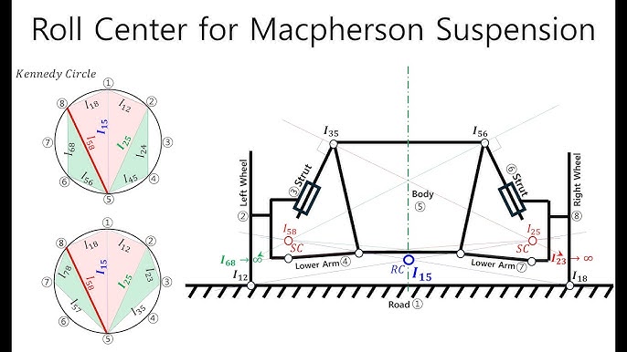
The roll center is the point about which the vehicle body rolls during cornering. Its height relative to the center of gravity determines weight transfer and roll stiffness. A higher roll center reduces body roll but can increase jacking forces. Calculate it from the instant centers of the front and rear suspensions.
Instant Center
The instant center is the point about which a suspension link rotates at a given instant. It determines the motion ratio and camber gain. For a double wishbone, it's found by intersecting the lines through the upper and lower control arm ball joints. For a MacPherson strut, it's the intersection of the strut axis and the lower control arm line.
Camber Gain
Camber gain is the change in camber angle per unit of wheel travel. It affects cornering grip and tire wear. Positive camber gain (camber increasing in negative direction as the wheel compresses) is desirable for cornering. Calculate it by plotting camber vs. wheel travel from your kinematic model.
Other Parameters
Toe change, scrub radius, anti-dive, and anti-squat also matter. Toe change affects stability during braking and cornering. Scrub radius influences steering feel and kickback. Anti-dive and anti-squat control suspension compression under braking and acceleration, affecting pitch. Each must be calculated and optimized for your application.
Step-by-Step Calculation of Suspension Kinematics: From Hardpoints to Graphs
Here's a practical methodology for calculating kinematics, whether you use software or manual methods.
Step 1: Gather Hardpoint Coordinates
Collect the 3D coordinates of all suspension attachment points—control arm pivots, strut mounts, ball joints, and wheel center. Use CAD data if available, or measure physically with a coordinate measuring machine (CMM) or laser scanner. Accuracy is critical; a 1 mm error can shift the roll center by 10 mm.
Step 2: Define the Suspension Type and Constraints
Identify the suspension architecture (MacPherson, double wishbone, multi-link) and its constraints. For example, a MacPherson strut has a fixed strut axis, while a double wishbone has two control arms. This determines the kinematic equations you'll use.
Step 3: Use a Kinematics Solver
Input the hardpoints into a kinematics solver—either commercial software like OptimumK or open-source tools like Suspension Analyzer. The solver computes instant centers, roll center, camber gain, and other parameters as the wheel moves through its travel. If doing manual calculations, use graphical methods: draw lines through the control arms to find instant centers, then project to find the roll center.
Step 4: Plot and Analyze Results
Generate plots of camber, toe, and roll center vs. wheel travel. Compare these against your design targets. For example, you might want -1° of camber gain per 50 mm of bump travel. If the graph shows excessive positive camber, you'll need to adjust hardpoints or arm lengths.
Choosing the Right Software: Commercial vs. Open-Source Kinematics Tools
Your choice of software depends on your budget, expertise, and need for accuracy.
Commercial Software
OptimumK, WinGeo, and VSusp are industry standards. They offer advanced features like compliance modeling, optimization, and export to CAD. They come with support and validation, but cost thousands of dollars per license. For professional engineers, the investment pays off in time saved and accuracy.
Open-Source Options
Free tools like Suspension Analyzer or custom scripts in MATLAB/Python can handle basic kinematics. They require more technical expertise to set up and lack support. However, they're ideal for hobbyists or students who want to learn the fundamentals without cost.
Comparison Criteria
When choosing, consider: ease of use, accuracy, ability to model compliance, export capabilities, and cost. If you're a hobbyist, open-source may suffice. If you're designing a race car, commercial software is worth the cost.
Kinematic vs. Compliance Effects: Why Static Calculations Aren't Enough
Kinematics assumes rigid links, but real suspensions have bushings that deflect under load. This compliance can significantly alter camber, toe, and roll center under cornering or braking. Ignoring it leads to inaccurate predictions and poor handling.
Advanced software can model compliance (elasto-kinematics) using bushing stiffness data. For example, a soft rear trailing arm bushing can cause toe-out under acceleration, affecting stability. To account for this, you need to input bushing rates into your model. If you're using a rigid-body tool, you'll need to validate with physical testing to capture compliance effects.
Validating Your Calculations: From Theory to Physical Testing
To ensure your calculations are accurate, you must validate them with physical testing.
Use a K&C Test Rig
A Kinematics & Compliance (K&C) rig measures actual suspension parameters by applying controlled loads and displacements. It provides data on camber, toe, and roll center as the suspension moves. Compare these measurements with your calculated values to identify discrepancies.
Adjust Your Model
If there's a mismatch, refine your model. Check hardpoint accuracy, bushing stiffness, and any assumptions you made. For example, if measured camber gain is less than calculated, your bushings may be deflecting more than expected. Update the model accordingly.
Road Testing
Finally, subjective road testing validates handling characteristics. If the car understeers more than predicted, your roll center or camber gain may be off. Use the data to make final adjustments.
Common Mistakes in Kinematics Calculation and How to Avoid Them
Avoid these frequent errors to save time and frustration.
Incorrect Hardpoint Data
Using wrong coordinates or units (e.g., inches vs. mm) will ruin your results. Always double-check your data and use consistent units.
Ignoring Compliance
As discussed, compliance can drastically change results. Always include bushing stiffness if you're modeling a real vehicle.
Misinterpreting Graphs
Don't confuse roll center with instant center. Roll center is a derived point from the instant centers of both sides. Understand what each graph represents before making changes.
Skipping Validation
Never trust a model without physical testing. Even small errors in hardpoints can lead to significant differences in real-world behavior.
Advanced Considerations: Elasto-Kinematics and Its Impact on Tire Wear
Elasto-kinematics combines geometry and compliance to predict tire contact patch behavior. This is crucial for optimizing tire life and performance.
Improper camber gain or toe change can cause uneven tire wear, such as inside edge wear from excessive negative camber. Advanced software can simulate tire wear patterns based on kinematic data, allowing you to adjust your setup before hitting the track.
For example, if your rear suspension has excessive toe change under load, it can scrub the tires and cause rapid wear. By modeling elasto-kinematics, you can identify the offending bushing and replace it with a stiffer one. Our [Large suspension bushing](/products/bushing-001-2) options are designed to minimize compliance and maintain geometry under load.
Understanding these effects is essential for any serious suspension engineer. It's the difference between a car that eats tires and one that wins races.
Conclusion and Expert Recommendations
Accurate suspension kinematics calculation is not optional—it's the foundation of vehicle dynamics. Start with a solid understanding of the key parameters, use the right tools, and always validate with physical testing. Whether you're a professional engineer or a dedicated enthusiast, mastering these calculations will transform your builds.
For your next project, consider investing in a quality kinematics software and a K&C test session. And remember, compliance matters—choose high-quality bushings that maintain geometry under load. Our range of [automotive suspension components](/products) includes precision-engineered bushings and control arms to support your suspension design.
If you're ready to take your suspension design to the next level, explore our [manufacturing facility](/manufacturing) and [quality control](/quality) processes to see how we ensure precision in every component. Learn more [about our company](/about) and how we can support your engineering needs.