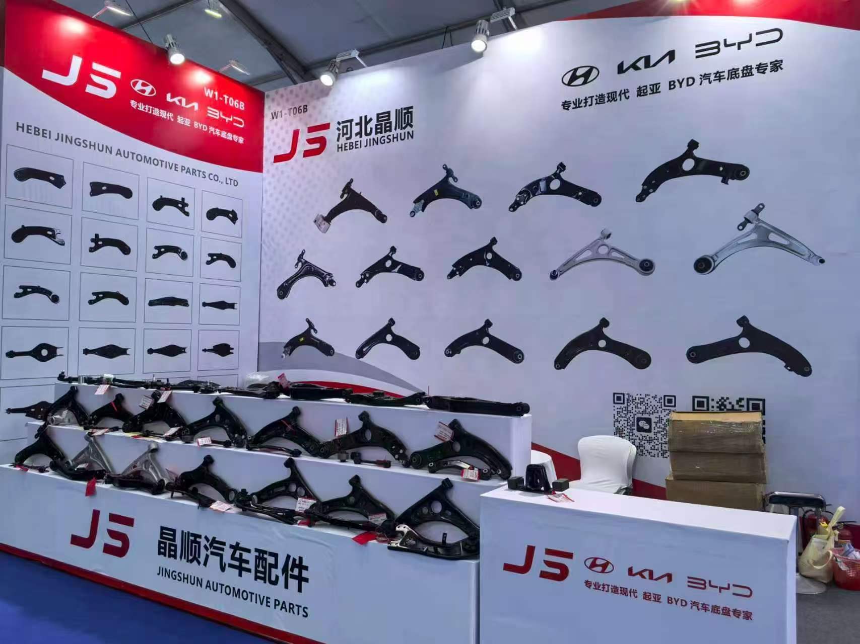
Trailing Arm Suspension Design: Pivot Location, Arm Length, and Bushing Compliance
Trailing arm suspension is a geometry problem before it is a parts problem. Pivot location, arm length, and bushing compliance set anti-squat, roll center, and tire wear. Get those three inputs right and the arm is a consequence of the design; get them wrong and no bushing or material upgrade will fix the handling. [MODEL_ANALYSIS]
This is the manufacturer's view: decide whether trailing arms suit the vehicle's requirements, design the geometry, then specify the arm and bushing. [MODEL_ANALYSIS]
Pure vs. Semi-Trailing Arm: Pivot Axis Orientation Decides Toe and Camber
A pure trailing arm keeps camber and toe nearly constant through travel because its pivot axis runs perpendicular to the vehicle centerline. A semi-trailing arm angles that axis in plan view, trading constant camber for tunable camber gain — and introducing toe change you must manage. The choice is not about which is "better"; it is about which behavior your vehicle's roll axis and packaging can tolerate. [MODEL_ANALYSIS]
In a pure trailing arm, the arm swings in a plane parallel to the vehicle's longitudinal axis. Vertical wheel travel produces almost no camber or toe change. That predictability is valuable in cost-sensitive and packaging-constrained rear suspensions, but it comes with a low roll center and minimal camber gain. If the body rolls in a corner, the outside tire loses camber relative to the road, reducing grip. [MODEL_ANALYSIS]
The semi-trailing arm solves part of that by angling the pivot axis in top view. The angle directly sets the rate of camber change per unit of vertical travel: a larger angle increases camber gain, which can compensate for body roll. The same angle also increases toe change. If that toe change is not matched to the vehicle's roll axis, you get unwanted bump steer — the rear end steers itself as the suspension compresses and rebounds. [MODEL_ANALYSIS]
Decision rule: choose a semi-trailing arm when you need camber compensation in roll and can tolerate or tune the toe variation. Choose a pure trailing arm when packaging simplicity and constant camber are the priorities, and you can control roll center through a separate lateral link. [MODEL_ANALYSIS]
Calculating Trailing Arm Geometry: Arm Length, Pivot Location, Anti-Squat, and Roll Center
Anti-squat percentage is set by the side-view swing arm angle — the angle of the line from the tire contact patch to the instant center. Your pivot height and arm length determine that angle. Roll center, by contrast, is located where the lateral restraint (Panhard rod or Watt's linkage) intersects the vehicle centerline; the trailing arms themselves do not define it the way they would in a double wishbone. [MODEL_ANALYSIS]
Start with a target anti-squat percentage. From that target, calculate the required instant center height using side-view geometry. Then solve for the pivot location and arm length that place the instant center where you need it. Finally, verify roll center using the lateral link geometry. [MODEL_ANALYSIS]
Arm length affects more than anti-squat. Longer arms reduce the angular change for a given vertical travel, which improves ride quality and reduces caster change, but it can also reduce anti-squat because the instant center moves. Shorter arms increase angular change and can raise anti-squat, but they also increase bushing deflection angles and packaging demands. [MODEL_ANALYSIS]
A practical sequence:
- Define target anti-squat percentage.
- Calculate required instant center height from side-view geometry.
- Solve for pivot location and arm length that place the instant center.
- Verify roll center with lateral link geometry.
This is iterative. Changing arm length to fix anti-squat will move the roll center if the lateral link is unchanged, so you must check both views together. [MODEL_ANALYSIS]
The Side-View Anti-Squat Relationship (Derived Geometry)
The following relationship is derived from standard side-view geometry; it is a design model, not measured test data. [MODEL_ANALYSIS]
Anti-squat % = (IC height / CG height) × (wheelbase / horizontal distance from contact patch to IC) × 100
Where:
- IC height = vertical height of the side-view instant center above ground
- CG height = vehicle center of gravity height above ground
- Wheelbase = longitudinal distance between front and rear axle centers
- Horizontal distance = longitudinal distance from the rear tire contact patch to the instant center
For a trailing arm, the instant center lies on the line through the pivot and the contact patch. If the arm is parallel to the ground, the IC is at the pivot height. If the arm is angled, the IC moves along that line.
Worked example:
Assume a rear-drive vehicle with:
- Wheelbase = 2700 mm
- CG height = 500 mm
- Target anti-squat = 30%
- Horizontal distance from contact patch to IC = 1500 mm
Solve for IC height:
30 = (IC height / 500) × (2700 / 1500) × 100
30 = (IC height / 500) × 1.8 × 100
30 = (IC height / 500) × 180
IC height = (30 × 500) / 180 = 83.3 mm
So the instant center must sit about 83 mm above ground. If the pivot is at 150 mm above ground and the arm is horizontal, the IC is at 150 mm — too high, giving more anti-squat than target. To bring the IC down to 83 mm, angle the arm downward toward the front (pivot lower than the contact patch line) or move the pivot. This is the kind of numeric check that turns a vague "calculate the IC" instruction into a decision. [MODEL_ANALYSIS]
Bushing Compliance: How It Changes Toe, Camber, and Tire Wear
Compliance in the trailing arm bushings allows the arm to deflect under cornering and braking loads, changing toe and camber dynamically. Softer bushings increase deflection and can cause unpredictable handling; stiffer bushings reduce deflection but transmit more noise and vibration. The bushing is not a passive part — it is a tuning element. [MODEL_ANALYSIS]
Symptoms of worn trailing arm bushings include uneven tire wear (especially inner or outer edge wear), clunking over bumps, vague steering, and rear-end instability during lane changes. These symptoms often appear gradually, so drivers may attribute them to tires or alignment rather than the bushings themselves. [MODEL_ANALYSIS]
Bushing material and design determine the trade-off between NVH isolation and geometric precision. Rubber offers good isolation and low cost but deflects more under load. Polyurethane reduces deflection and improves consistency but increases NVH. Spherical bearings eliminate compliance almost entirely but are harsh and require maintenance. The choice must match the vehicle's intended use — a daily driver and a track car should not use the same bushing. [MODEL_ANALYSIS]
Specify the bushing's radial and axial stiffness based on the loads the arm sees and the desired amount of compliance. Too stiff can cause suspension bind; too soft can cause excessive toe change. For Hyundai and Kia applications, JS Suspension offers a range of rear trailing arm bushings, including Rear Trailing Arm Bushing — 55274-D3000 and Rear Trailing Arm Bushing — 55274-2W000, as well as large suspension bushings such as Large suspension bushing — 54584-2D000 and Large suspension bushing — 54584-3S100. [FACT_FROM_DATABASE]
Fitment and specification data (from database):
| Part number | Position | Material / stiffness | Fitment notes |
|---|---|---|---|
| 55274-D3000 | Rear trailing arm | Data unavailable | Data unavailable |
| 55274-2W000 | Rear trailing arm | Data unavailable | Data unavailable |
| 54584-2D000 | Large suspension bushing | Data unavailable | Data unavailable |
| 54584-3S100 | Large suspension bushing | Data unavailable | Data unavailable |
Only the part numbers, position (rear trailing arm / large suspension bushing), and the fact that they are offered for Hyundai/Kia applications are confirmed in the database. Durometer, construction, and exact chassis-year fitment are not available in the supplied data. [FACT_FROM_DATABASE]
Material Selection and Fabrication for Custom Trailing Arms
Mild steel is cost-effective and easy to weld, but it is heavy. Chromoly steel offers a higher strength-to-weight ratio, but it requires proper welding and heat treatment to avoid cracking. Aluminum is lightweight but requires careful design to avoid fatigue failures. The right choice depends on stress levels, weight targets, and fabrication capability. [MODEL_ANALYSIS]
Welding quality is critical. Stress relief and proper joint design prevent cracking. For aluminum, TIG welding and post-weld heat treatment may be necessary. Design for manufacturability: consider tube vs. plate construction, bushing housing integration, and ease of alignment during assembly. [MODEL_ANALYSIS]
Decision factors: use mild steel for low-cost, low-stress applications; chromoly for high-performance or weight-sensitive builds; aluminum only when weight is critical and fatigue analysis is performed. [MODEL_ANALYSIS]
Step-by-Step Design Process: From Requirements to CAD and FEA Validation
Step 1: Define requirements — vehicle weight, intended use, target anti-squat, roll center height, camber curve, and packaging constraints. [MODEL_ANALYSIS]
Step 2: Preliminary geometry — calculate arm length and pivot locations using the methods from the geometry section; iterate until targets are met. [MODEL_ANALYSIS]
Step 3: CAD modeling — create a 3D assembly to check packaging, suspension travel, and interference with other components. [MODEL_ANALYSIS]
Step 4: FEA — analyze stresses under braking, cornering, and bump loads; optimize material thickness and joint design. [MODEL_ANALYSIS]
Step 5: Validation — if possible, build a prototype and measure kinematics on a suspension rig or through on-vehicle testing; compare to targets. [MODEL_ANALYSIS]
Common Trailing Arm Design Mistakes and How to Avoid Them
Mistake 1: Ignoring bushing compliance in the geometry calculation — always account for deflection under load. [MODEL_ANALYSIS]
Mistake 2: Placing the pivot axis without considering anti-squat and roll center interactions — use a side-view and rear-view layout simultaneously. [MODEL_ANALYSIS]
Mistake 3: Overlooking packaging and suspension travel — ensure the arm does not bind or contact other components through full jounce and rebound. [MODEL_ANALYSIS]
Mistake 4: Using insufficient material or poor weld quality — perform FEA and follow welding best practices. [MODEL_ANALYSIS]
Mistake 5: Not validating the design — even a simple kinematic check can catch major errors before fabrication. [MODEL_ANALYSIS]
When Trailing Arms Are the Right Architecture — and When They Are Not
Trailing arms are the right choice when packaging is tight (especially for rear suspension in FWD-based vehicles), cost and simplicity are priorities, and the required roll center and camber behavior can be met with a semi-trailing or pure trailing design plus a lateral link. [MODEL_ANALYSIS]
Trailing arms are the wrong choice when precise camber control in roll is critical (e.g., high-performance independent rear suspension), or when the desired roll center height and migration cannot be achieved without excessive toe change. [MODEL_ANALYSIS]
Alternative architectures: double wishbone or multi-link offer better camber and roll center control but at higher cost and complexity; the decision should be based on the vehicle's mission, not on trend. [MODEL_ANALYSIS]
Manufacturer's perspective: design the geometry first, then specify the arm and bushing; the arm is a consequence of the geometry, not the starting point. [MODEL_ANALYSIS]
FAQ
Do trailing arms define the rear roll center?
No. In a trailing arm layout, roll center is located where the lateral restraint — Panhard rod or Watt's linkage — intersects the vehicle centerline. The trailing arms themselves do not define it the way they would in a double wishbone. [MODEL_ANALYSIS]
What sets anti-squat in a trailing arm suspension?
Anti-squat percentage is set by the side-view swing arm angle — the angle of the line from the tire contact patch to the instant center. Pivot height and arm length determine that angle. [MODEL_ANALYSIS]
When should I choose a semi-trailing arm over a pure trailing arm?
Choose a semi-trailing arm when you need camber compensation in roll and can tolerate or tune the toe variation. Choose a pure trailing arm when packaging simplicity and constant camber are the priorities, and you can control roll center through a separate lateral link. [MODEL_ANALYSIS]
How does bushing compliance affect tire wear?
Compliance in the trailing arm bushings allows the arm to deflect under cornering and braking loads, changing toe and camber dynamically. Too soft can cause excessive toe change and uneven tire wear; too stiff can cause suspension bind. Specify radial and axial stiffness based on the loads the arm sees and the desired amount of compliance. [MODEL_ANALYSIS]