Suspension Motion Ratio Is Not a Constant: How to Measure the Curve and Pick the Right Springs and Dampers
Motion ratio is the ratio of spring or damper travel to wheel travel, and it changes as the suspension compresses and extends. If you treat it as one fixed number—from a forum post or a single measurement at ride height—your wheel rate calculation will be wrong, your spring rate will be wrong, and your damper valving will be wrong. The geometry between the lower control arm, spring perch, and damper mounts shifts continuously through travel, so the ratio between wheel movement and spring movement is never constant.
A spring that feels correct at ride height can be too soft in compression or too stiff in droop. That shows up as inconsistent roll stiffness, poor bump absorption, and handling that changes mid-corner. The fix is to measure motion ratio across the full suspension range and work with the resulting curve, not a single value.
Motion Ratio vs. Installation Ratio: Which One Goes Into the Wheel-Rate Formula
Motion ratio (MR) is the ratio of spring or damper travel to wheel travel. If the wheel moves 50 mm and the spring compresses 25 mm, the motion ratio is 0.5. Installation ratio (IR) accounts for the angle of the spring or damper relative to the control arm—it is the motion ratio multiplied by the cosine of that angle.
When you calculate wheel rate, you square the installation ratio, not the raw motion ratio:
Wheel rate = spring rate × IR²
If the spring or damper is perpendicular to the control arm, IR equals MR and the distinction does not matter. On most real suspensions, the spring or damper sits at an angle, so IR is smaller than MR. Using MR instead of IR overstates wheel rate. Always confirm whether a published value is a motion ratio or an installation ratio, and whether it already includes the angle correction.
A small error compounds because of the square. If you use 0.5 instead of the actual 0.55, your wheel rate calculation is off by roughly 17%. That error translates directly into wrong spring rate choices and mismatched damper valving.
How Motion Ratio Affects Spring Rate, Wheel Rate, and Suspension Frequency
Wheel rate is spring rate multiplied by the square of installation ratio. An installation ratio of 0.5 reduces wheel rate to 25% of spring rate. If you install a 10 kg/mm spring with an installation ratio of 0.5, the wheel sees only 2.5 kg/mm. That is why a spring that seems stiff on paper can feel soft at the wheel.
Suspension frequency (natural frequency) depends on wheel rate and sprung mass. Changing motion ratio alters frequency without changing the spring itself. A higher motion ratio increases wheel rate and raises frequency; a lower motion ratio does the opposite.
Damper valving must also account for motion ratio because damper shaft velocity differs from wheel velocity. If the damper moves slower than the wheel, the damping force at the wheel is lower than the damper's rated force. Ignoring this leads to under-damped or over-damped behavior.
Non-Linear Motion Ratio: Why the Curve Matters More Than the Number
As the suspension compresses, the angle between the control arm and the spring or damper changes, altering the lever arm ratio. Motion ratio is not constant—it varies with travel. A non-linear motion ratio means wheel rate changes with travel, affecting roll stiffness, ride height sensitivity, and bump absorption.
Plotting motion ratio versus suspension travel reveals the curve. Ignoring it leads to springs that are too stiff in bump or too soft in droop. For example, a suspension that starts at 0.6 motion ratio at ride height might drop to 0.5 at full compression. That 17% change in motion ratio translates to a 30% change in wheel rate, which can make the car unpredictable at the limit.
Worked Example: Wheel Rate at Ride Height vs. Full Bump
Suppose you measure a curve that gives IR = 0.55 at ride height and IR = 0.45 at full bump. You are running a 10 kg/mm spring.
- Wheel rate at ride height = 10 × 0.55² = 10 × 0.3025 = 3.03 kg/mm
- Wheel rate at full bump = 10 × 0.45² = 10 × 0.2025 = 2.03 kg/mm
That is a 33% drop in wheel rate from ride height to full bump. If you had used the ride-height value alone, you would have sized the spring for 3.03 kg/mm and never accounted for the softness in compression. The car will feel stiffer than expected in bump and may bottom out or lose roll stiffness at the limit.
Step-by-Step: Measuring Motion Ratio on Your Vehicle
Measuring the curve requires isolating wheel travel from spring or damper travel. The method depends on your suspension type.
Preparation and Safety
- Work on a level surface with the vehicle supported on jack stands under the chassis, not under the control arm.
- Disconnect the sway bar end links on both sides so the suspension moves freely and independently.
- Remove the spring or damper only if the suspension design allows it safely. On a MacPherson strut, the spring is often the load-bearing element—do not remove it unless you have a spring compressor and a safe procedure. On a double wishbone, you can often disconnect the damper and cycle the suspension without the spring.
- Use a floor jack under the control arm to compress the suspension smoothly. Never put any part of your body under the vehicle while the suspension is being cycled.
What to Measure and Record
- Measure wheel travel at the hub or wheel center. Use a dial indicator or a travel indicator mounted to a fixed point on the chassis.
- Measure spring or damper travel at the spring perch or damper shaft. Use calipers or a second dial indicator.
- Record data at every 10 mm of wheel travel from full droop to full bump. At each increment, record wheel travel, spring travel, and damper travel separately.
- Calculate the ratio at each increment: spring travel ÷ wheel travel = spring MR; damper travel ÷ wheel travel = damper MR.
- Plot the data to see the motion ratio curve. Repeat for both sides and average if needed.
Isolating Wheel Travel on MacPherson Strut vs. Double Wishbone
- MacPherson strut: The strut is the load-bearing member. Disconnect the sway bar, support the hub with a jack, and measure strut travel at the shaft. Do not remove the spring unless you have the correct spring compressor and a safe procedure. The strut angle changes with travel, so the motion ratio curve is often steeper than on a double wishbone.
- Double wishbone: Disconnect the sway bar and the damper. Cycle the suspension through its range and measure wheel travel at the hub and spring travel at the spring perch. If the spring and damper are not coaxial, measure each separately—they will have different motion ratios.
Motion Ratio in MacPherson Strut vs. Double Wishbone: What Changes and Why It Matters
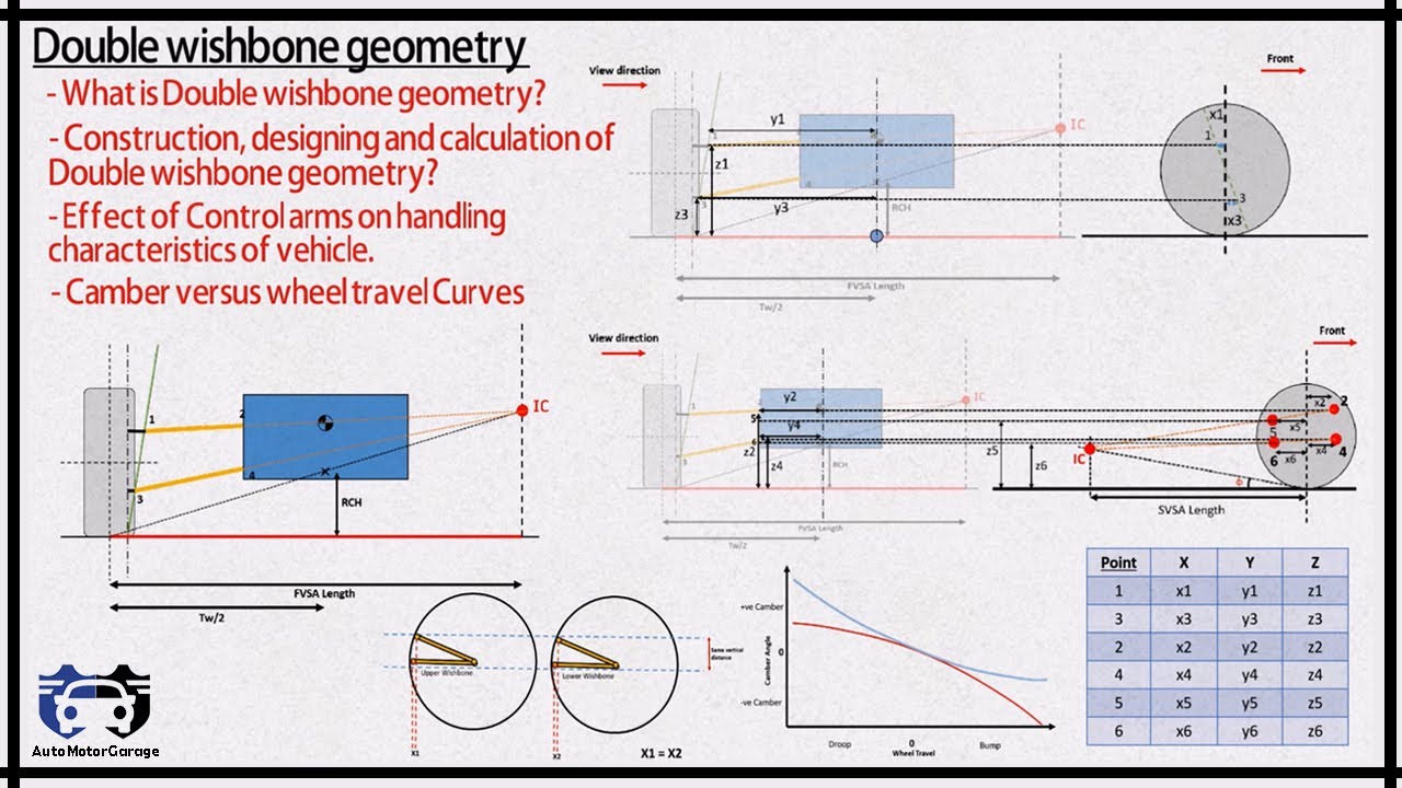
MacPherson struts often have motion ratios closer to 1.0 because the strut acts directly on the wheel carrier. However, they can vary more with travel due to strut angle changes. Double wishbone suspensions can be designed for more consistent motion ratio but still exhibit non-linearity depending on arm lengths and pivot locations.
Understanding your suspension type helps interpret measured motion ratio and predict handling traits. A MacPherson strut with a motion ratio that drops significantly in compression will have a wheel rate that falls off, leading to understeer or poor bump absorption. A double wishbone with a flatter curve will maintain more consistent wheel rate, which is why it is preferred in performance applications.
When Spring and Damper Are Not Coaxial
On many double wishbone suspensions, the spring sits on a perch on the lower control arm while the damper mounts to a different point. They do not share the same motion ratio. You must measure spring MR and damper MR separately.
- Use spring MR (and its angle correction) to calculate wheel rate from spring rate.
- Use damper MR to calculate damper shaft velocity from wheel velocity, which determines damping force at the wheel.
If you use the spring MR for damper calculations, your damping force will be wrong. For example, if the spring MR is 0.6 and the damper MR is 0.5, a wheel velocity of 100 mm/s gives a damper shaft velocity of 50 mm/s, not 60 mm/s. That 20% difference changes the damping force the damper produces at that shaft speed.
Common Mistakes in Motion Ratio Calculations and How to Avoid Them
- Using a single motion ratio value from a static measurement or online source without verifying across travel.
- Forgetting to square the installation ratio when calculating wheel rate from spring rate.
- Ignoring the angle correction when the spring or damper is not perpendicular to the control arm.
- Using the spring motion ratio for damper calculations when the spring and damper are not coaxial.
To avoid these, always measure the curve, not just one point. Double-check whether your motion ratio already includes the angle correction. Use the squared installation ratio for wheel rate calculations. And never assume that a value from a different vehicle or setup applies to yours—suspension geometry varies widely.
Applying the Motion Ratio Curve: Selecting Springs and Dampers for Your Setup
Use the motion ratio curve to calculate wheel rate at ride height and through travel, then choose spring rates that deliver target wheel rates. Match damper valving to the motion ratio so that damping forces at the wheel are appropriate for the sprung mass and intended use. Consider suspension frequency targets—1.5–2.5 Hz for street, higher for track—and adjust spring rate and motion ratio accordingly.
Worked Example: Target Wheel Rate to Spring Rate to Damper Adjustment
Suppose you want a target wheel rate of 3.0 kg/mm at ride height. Your measured installation ratio at ride height is 0.55.
- Required spring rate = target wheel rate ÷ IR² = 3.0 ÷ 0.3025 = 9.9 kg/mm
You would select a 10 kg/mm spring. Now check the damper. Your damper motion ratio is 0.5. At a wheel velocity of 100 mm/s, the damper shaft velocity is 50 mm/s. If your damper is valved for 100 mm/s shaft speed, it will produce less force at 50 mm/s. You may need to increase rebound and compression damping to compensate, or select a damper with a valving curve that matches your actual shaft speeds.
For example, if the damper produces 200 N at 100 mm/s and you need 200 N at the wheel, but the damper only sees 50 mm/s, you need a damper that produces 200 N at 50 mm/s. That may mean a different valving stack or a different damper altogether. Always verify the damper's force-velocity curve against your calculated shaft speeds.
Verifying Motion Ratio After Installation or Alignment Changes
After installing new springs, dampers, or control arms, or after an alignment change, re-measure motion ratio at ride height. Ride height changes alter the suspension's position in its travel, which changes the motion ratio. A 10 mm ride height change can shift the motion ratio enough to affect wheel rate. If you cannot re-measure the full curve, at least measure at the new ride height and compare to your original curve. If the value has shifted, your wheel rate and damper behavior have changed.
When selecting suspension components, remember that bushings and control arms also affect motion ratio. Worn bushings can change geometry under load, altering the effective motion ratio. Upgrading to new control arms or bushings—such as Large suspension bushing — 54584-2D000 or Large suspension bushing — 54584-3S100—can restore or modify suspension geometry. Always verify motion ratio after any suspension component change.
For accurate spring and damper selection, measure your motion ratio curve, calculate wheel rates, and choose components that match your target frequency and damping. This approach eliminates guesswork and delivers predictable handling.
---
Related