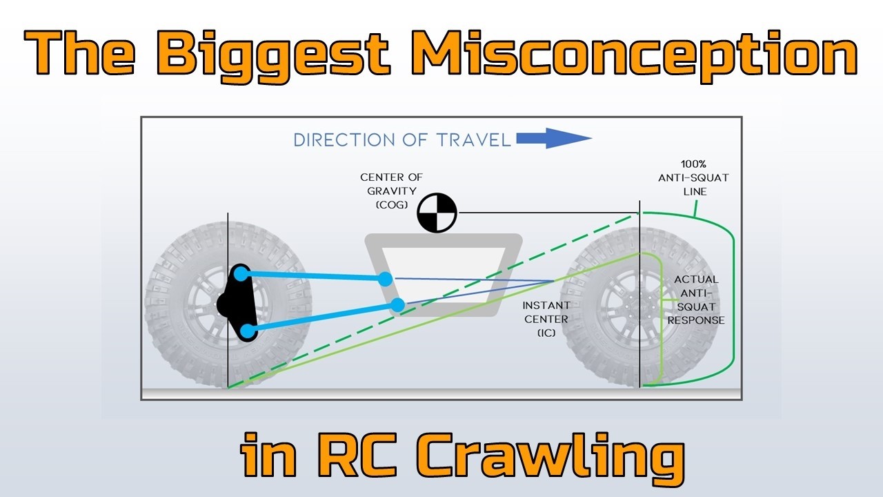
Anti-Squat Is a Tuning Variable, Not a Target
The correct anti-squat percentage is the one that matches your traction goal and chassis constraints—not a mythical ideal number. Anti-squat describes how much the rear suspension resists squat under acceleration by redirecting force through the links instead of the springs. [SEARCH_EVIDENCE] There is no universal ideal percentage. Drag, road course, off-road, and street comfort each demand different anti-squat behavior. [MODEL_ANALYSIS]
A drag car wants high anti-squat to plant the tires and minimize power loss to suspension compression. A road course car needs moderate anti-squat to maintain corner-exit grip without upsetting balance. An off-road truck may want low anti-squat to absorb bumps without kicking the rear up. A street car prioritizes comfort, so low anti-squat with soft springs is often best.
The Decision Framework
Define traction goal → define chassis constraint (ride height, link packaging, roll center) → choose anti-squat range → test and iterate. [MODEL_ANALYSIS]
Blindly increasing anti-squat can reduce rear grip on corner exit, increase tire temperature sensitivity, and degrade ride quality. [MODEL_ANALYSIS] Start by writing down what you need: maximum straight-line traction, balanced cornering, or a comfortable ride. Then measure your current geometry and calculate your baseline anti-squat. Only then should you consider adjustments.
The Physics You Actually Need: Instant Center, CG Height, and Anti-Squat Percentage
Anti-squat percentage is calculated from the side-view instant center (IC) location and the center of gravity (CG) height. The formula is:
Anti-squat % = (IC height at rear axle / CG height) × 100 [SEARCH_EVIDENCE]
The instant center is found by extending the lines of the rear suspension links (or virtual swing arm) in side view. [SEARCH_EVIDENCE] Where those lines intersect is your IC. The height of that point relative to the ground, divided by the CG height, gives you a ratio. Multiply by 100 for percentage.
A 100% anti-squat value means the suspension geometry completely resists squat at that instant; values above 100% can cause the rear to rise under acceleration. [SEARCH_EVIDENCE] Anti-squat is not a static number—it changes with ride height, load, and suspension travel. [MODEL_ANALYSIS] As the suspension compresses or extends, the link angles change, moving the IC and altering anti-squat. This is why a car that works perfectly at ride height may behave differently when loaded with passengers or under braking.
Worked Example: Calculating Anti-Squat from Four Measurements
To calculate your anti-squat, you need four measurements:
- Rear axle centerline height (from ground)
- CG height (from ground)
- Lower link length (pivot to pivot)
- Lower link angle (degrees from horizontal)
Example: [MODEL_ANALYSIS]
- Axle centerline height: 12 in
- CG height: 20 in
- Lower link length: 24 in
- Lower link angle: 5° (rising toward chassis)
Step 1: Find the IC height. For a simple trailing-arm geometry, the IC height is approximately the axle centerline height plus the vertical rise of the link over its length. Vertical rise = link length × sin(angle) = 24 × sin(5°) ≈ 2.1 in. IC height ≈ 12 + 2.1 = 14.1 in.
Step 2: Apply the formula. Anti-squat % = (14.1 / 20) × 100 = 70.5%.
This is a simplified model. Real suspensions with multiple links require extending all link lines to find the true IC. But the principle holds: measure, calculate, then test. [MODEL_ANALYSIS]
How Anti-Squat Affects Traction, Weight Transfer, and Handling Balance
Higher anti-squat increases rear tire load under acceleration by reducing squat, which can improve straight-line traction but may reduce corner-exit grip if it unloads the inside rear tire. [SEARCH_EVIDENCE] When you accelerate, weight transfers rearward. With low anti-squat, the rear springs compress, absorbing some of that energy. With high anti-squat, the links resist compression, so more force goes directly into the tire. That can be great for launching, but in a corner, the inside rear tire may lift, reducing grip.
Anti-squat affects the rate of weight transfer, not the total amount. It changes how quickly load transfers to the rear tires. [MODEL_ANALYSIS] Total weight transfer is determined by CG height, wheelbase, and acceleration. Anti-squat only changes the timing and distribution between sprung and unsprung mass. Excessive anti-squat can cause the rear to rise, leading to loss of camber and reduced contact patch. [MODEL_ANALYSIS] If the rear rises, the camber curve may go positive, tilting the tire so only the outer edge contacts the road. That kills grip.
Anti-squat interacts with roll center and camber curves; changing one affects the others. [MODEL_ANALYSIS] Moving link mounts to alter anti-squat often changes the roll center height, which affects cornering balance. Similarly, camber curves are tied to link geometry. You cannot tune anti-squat in isolation.
Adjusting Anti-Squat: Link Lengths, Mounting Points, and Aftermarket Components
Changing the length or angle of rear suspension links (e.g., trailing arms, lower control arms) moves the instant center and changes anti-squat. [SEARCH_EVIDENCE] Lengthening the lower link or changing its angle at the chassis can raise or lower the IC. Relocating mounting points on the chassis or axle is a more permanent adjustment that requires fabrication or aftermarket brackets. [SEARCH_EVIDENCE]
Aftermarket adjustable links, relocation brackets, and torque arms allow anti-squat tuning without cutting or welding. [MODEL_ANALYSIS] Adjustments should be made in small increments and tested, because anti-squat changes can have non-linear effects. [MODEL_ANALYSIS]
For many Hyundai and Kia models, the rear suspension uses trailing arms and control arms. Upgrading worn bushings to stiffer units can reduce deflection, making anti-squat more consistent under load. For example, replacing the rear trailing arm bushing with a new OEM or performance bushing can restore intended geometry. [FACT_FROM_DATABASE] Similarly, control arms can be replaced with adjustable versions if available. [FACT_FROM_DATABASE] However, most street cars have limited adjustment from the factory. Aftermarket companies offer brackets that relocate the lower control arm mounting point, effectively changing the IC.
What to Look For in Aftermarket Anti-Squat Components
When evaluating aftermarket parts, focus on these decision criteria:
- Adjustment range: How many mounting positions? What anti-squat change does each position provide? A bracket with three holes might offer a 20–30% range; a race part with five holes might offer 40–50%. [MODEL_ANALYSIS]
- Material and thickness: Steel brackets should be at least 3/16 in thick for street use, 1/4 in for race. Check for reinforced gussets at load points. [MODEL_ANALYSIS]
- Installation method: Bolt-on brackets preserve factory mounting points and are reversible. Weld-on kits offer greater rigidity but require fabrication. [MODEL_ANALYSIS]
- Bushing compatibility: Stiffer bushings reduce deflection but increase NVH. Polyurethane is a common compromise; spherical bearings are for race only. [MODEL_ANALYSIS]
- Corrosion protection: Powder coat or zinc plating matters for street cars. [MODEL_ANALYSIS]
When adjusting, always measure your starting point. Use a plumb bob and tape measure to find the heights of the links and the CG. Then make one change at a time. If you lengthen the lower link by 10mm, recalculate anti-squat and test. Keep a log of changes and results.
Trade-Offs: Anti-Squat vs. Ride Comfort, Roll Center, and Camber
Higher anti-squat often requires stiffer rear springs or more aggressive link angles, which can degrade ride comfort. [MODEL_ANALYSIS] Stiffer springs resist compression, but they also transmit more road noise and harshness. Aggressive link angles can bind or wear bushings faster. Changing anti-squat by moving link mounting points can also change the roll center height, affecting cornering balance. [MODEL_ANALYSIS] A higher roll center reduces body roll but can cause jacking and unpredictable handling. Anti-squat adjustments can alter camber curves, affecting tire wear and grip. [MODEL_ANALYSIS] If you raise the rear ride height to increase anti-squat, you may gain negative camber, which helps cornering but wears the inside edge of the tire.
There is no free lunch: improving straight-line traction may hurt cornering or comfort. [MODEL_ANALYSIS] A drag car with 100% anti-squat will launch hard but may feel unstable in turns. A road course car with 50% anti-squat will corner well but may spin the tires on exit. You must prioritize.
Common Mistakes and Pitfalls When Tuning Anti-Squat
Assuming higher anti-squat is always better: it can cause rear rise, loss of camber, and reduced corner-exit grip. [MODEL_ANALYSIS] Many enthusiasts think more anti-squat equals more traction, but that's only true in a straight line.
Ignoring the effect of ride height and load on anti-squat: the percentage changes with suspension travel. [MODEL_ANALYSIS] If you set anti-squat at static ride height, it may drop to 70% when the car squats under load.
Making multiple changes at once: it becomes impossible to isolate the effect of anti-squat. [MODEL_ANALYSIS] Change one thing, test, then change another.
Not measuring: guessing at instant center location leads to incorrect calculations. [MODEL_ANALYSIS] You cannot tune what you haven't measured.
Another pitfall is overlooking bushing deflection. Worn or soft bushings allow the links to move under load, changing the effective geometry. Upgrading to stiffer bushings can make anti-squat more predictable. [FACT_FROM_DATABASE] But stiffer bushings also increase NVH.
Manufacturer Perspective: Designing Adjustable Anti-Squat Components
Adjustable components typically offer a range of mounting positions or link lengths to change instant center. [MODEL_ANALYSIS] Manufacturers must balance adjustment range with structural integrity and ease of use. [MODEL_ANALYSIS] A bracket with multiple holes must be strong enough to withstand suspension loads, yet easy to install with basic tools. Some designs prioritize street comfort with limited adjustment, while race-oriented parts offer wider ranges. [MODEL_ANALYSIS] Understanding the design intent helps buyers choose the right product for their use case. [MODEL_ANALYSIS]
When shopping, look at the adjustment range, material thickness, and installation requirements. If you have a daily driver, you might prefer a bolt-on bracket with a modest range. If you have a dedicated race car, a weld-on kit with a wide range is better.
Putting It Into Practice: A Step-by-Step Tuning Process for Your Vehicle
Step 1: Measure your current suspension geometry to calculate baseline anti-squat. [MODEL_ANALYSIS] Park the car on a level surface. Measure the heights of the lower link pivots and the axle centerline. For CG height, use a scale-based method: weigh the car at each axle, then use the formula CG height = (rear weight × wheelbase) / total weight × (1 / tan(angle)) — or consult a chassis shop. Approximating from engine height is a rough estimate with ±2 in error. [MODEL_ANALYSIS]
Step 2: Define your primary goal (drag launch, corner exit, comfort) and choose a target anti-squat range. [MODEL_ANALYSIS] These are starting points, not universal targets. Actual values depend on CG height, wheelbase, and tire compound. For drag racing, a common starting range is 80–100%. For road racing, 50–70%. For street comfort, 30–50%. [MODEL_ANALYSIS]
Step 3: Make one adjustment at a time and test under consistent conditions. [MODEL_ANALYSIS] Use the same road or track, same tire pressures, and same weather if possible.
Step 4: Record changes in lap times, 60-ft times, or subjective feel, and iterate. [MODEL_ANALYSIS] Keep a notebook. If a change makes the car worse, revert it.
Remember that anti-squat is just one variable. Tire choice, spring rates, and dampers all play a role. But by understanding and tuning anti-squat, you can unlock traction and balance that otherwise seem impossible.
---
Related