Suspension Kinematics Analysis: How to Read Roll Center Migration, Camber Curves, and Bump Steer to Choose Components

Suspension kinematics analysis tells you how your suspension geometry moves — nothing more. It does not predict tire grip, compliance effects, or on-track balance. If you are using it to choose arm lengths, pickup points, or ball joint travel, you are using it correctly. If you are using it to claim a lap-time improvement, you are overstepping its boundaries.
Kinematics outputs — roll center migration, camber gain, bump steer, motion ratio, anti-dive, and anti-squat — are purely geometric. They assume rigid links and rigid bushings. Real suspensions flex under load, tires slip, and dampers behave nonlinearly. Those effects live outside the kinematic model. The value of running a kinematic sweep is not the plot itself; it is the interpretation against a specific vehicle application. A road car, a track-day car, and a purpose-built race car have different targets for roll center migration, camber gain, and bump steer. What looks acceptable on a street car may be unacceptable on a formula car.
The software is the easy part. OptimumKinematics, or any equivalent tool, will produce curves once you input hardpoints and define a sweep. The skill is reading those curves and translating them into decisions: should the upper control arm be longer? Does the inner tie rod pivot need to move up or down? Is the motion ratio curve flat enough for the damper you plan to run? This article walks through that translation.
Building the Kinematic Model: Hardpoints, Motion Ratio, and the Sweep That Produces Usable Curves
A kinematic model is only as good as its hardpoints. Measure or extract from CAD the following points before opening the software: lower control arm inner and outer pivots, upper control arm inner and outer pivots, ball joint centers, tie rod inner and outer points, steering rack travel limits, and wheel center. Guessing these coordinates produces curves that look plausible but mislead every downstream decision.
Once hardpoints are in, define the spring and damper attachment points. Confirm the motion ratio curve across the intended wheel travel before running any sweep. Motion ratio is the ratio of spring/damper travel to wheel travel. A motion ratio that changes significantly through bump means the damper sees a different effective rate at different ride heights — that affects valving and spring selection. Plot it. If the curve is not smooth or falls outside a plausible range for your suspension type, fix the attachment points before proceeding.
Sweep definition depends on application. A road car might sweep ±80 mm of wheel travel, ±20° of steering, and ±3° of roll. A race car might sweep ±30 mm, ±10° of steering, and ±2° of roll. The sweep must match the vehicle's real operating range. A sweep that is too wide produces curves that never occur on track; too narrow and you miss the problematic region.
Before interpreting anything, run sanity checks. Does the bump curve look symmetric left-to-right? Is the motion ratio plausible (typically 0.4–0.7 for a double-wishbone, depending on layout)? Are there solver warnings about link interference or undefined constraints? Fix these first. A model with solver warnings will produce garbage curves.
Reading Roll Center Migration: What 'Good' Looks Like for Road, Track-Day, and Race Applications
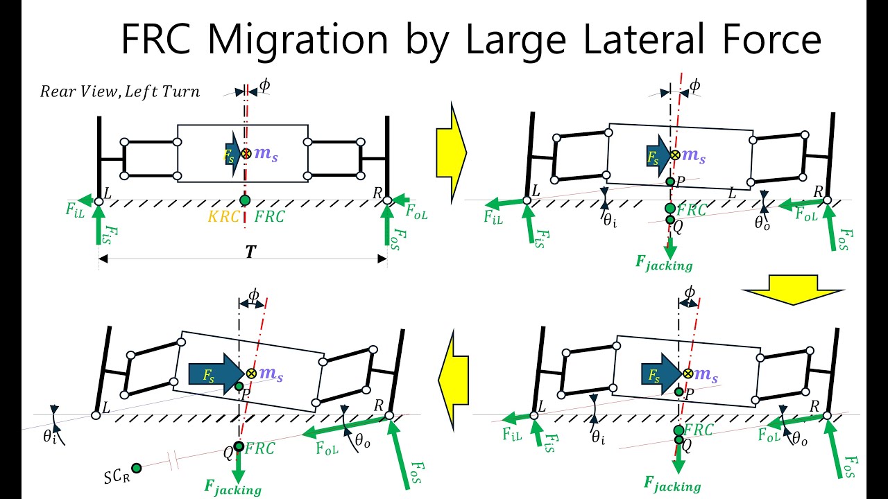
Roll center height is a starting number. Migration is the curve that drives handling decisions. You need to look at two types of migration: lateral (roll center moving side-to-side under roll) and vertical (moving up/down under bump). They have different consequences.
Lateral migration changes the roll moment arm as the car rolls. A roll center that moves 100 mm laterally under 2° of roll will produce inconsistent roll stiffness and a nonlinear steering feel. Vertical migration changes the jacking force and the roll center height relative to the center of gravity. A roll center that drops below ground under bump is a geometry red flag — it flips the sign of the roll moment and usually indicates a hardpoint problem, not a tuning preference.
Application benchmarks: A road car tolerates more migration for ride comfort. Lateral migration of 50–80 mm across full roll may be acceptable if the driver never notices. A track-day car wants tighter control — aim for less than 40 mm lateral migration within the working roll range. A purpose-built race car typically targets minimal lateral migration (under 20 mm) and a vertical migration that keeps the roll center above ground throughout the bump range. These are starting points, not absolutes. The right target depends on tire characteristics, aero load, and driver preference — but you need a target before you can judge the curve.
If your roll center migrates excessively, the fix is usually in the inner pivot heights of the upper and lower control arms. Raising or lowering the inner pivots changes the instant center location and therefore the roll center. This is a high-leverage change — small pivot moves produce large migration changes.
Camber Gain, Bump Steer, Motion Ratio, and Anti-Dive/Anti-Squat: The Curves That Drive Component Choices
Camber gain is the rate of camber change per unit of bump travel. Too little and the tire loses contact patch under roll; too much and the inner tire overheats. The fix is usually upper arm length or inner pivot height. A longer upper arm reduces camber gain; a shorter one increases it. Moving the inner pivot up or down changes the rate at which camber builds. Plot camber gain against bump travel and compare to your target — typically 0.5–1.0°/inch for a race car, less for a road car.
Bump steer is toe change per unit of bump travel. Excessive bump steer is almost always a tie rod inner pivot height or length problem, not a steering rack problem. The tie rod must follow the same arc as the control arm to avoid toe change. If the inner pivot is too high or too low, the tie rod and control arm arcs diverge, producing bump steer. The fix is pivot relocation — moving the inner tie rod point up or down to match the control arm arc.
Motion ratio is the curve shape, not just the static number. A motion ratio that rises steeply in bump means the spring rate effectively increases, which can cause a harsh ride or unexpected load transfer. A motion ratio that falls in bump means the damper loses effectiveness. The curve shape determines spring and damper selection and whether the damper has usable travel. If the motion ratio curve is not relatively flat through the intended travel, relocate the spring/damper attachment points.
Anti-dive and anti-squat are side-view geometry parameters that affect braking and acceleration stability. Anti-dive is the percentage of braking force that resists dive; anti-squat is the percentage of acceleration force that resists squat. These are set by the upper and lower arm pivot heights in side view. The fix is in the pivot heights, not in the springs. A car with too little anti-dive will dive excessively under braking; too much can cause brake hop. Plot the anti-dive and anti-squat percentages against suspension travel and compare to typical targets (10–30% for a road car, 20–50% for a race car).
Troubleshooting Common Geometry Problems Revealed by Kinematics Analysis
Excessive bump steer: symptom is toe change across bump. Cause is tie rod inner pivot height or length mismatch with the control arm arc. Fix is pivot relocation, not rack replacement. Move the inner tie rod point up or down until the toe change curve flattens.
Roll center below ground: symptom is a sign flip in the roll moment curve. Cause is upper and lower arm pivot height relationship. Fix is inner pivot height adjustment. Raise the inner pivots or change the arm length ratio to bring the roll center above ground throughout the bump range.
Poor camber curve: symptom is camber gain that is too flat or too aggressive. Cause is upper arm length or inner pivot height. Fix is arm geometry, not static camber adjustment. Static camber changes the starting point; it does not change the rate of camber gain. If the curve shape is wrong, you need to change the arm lengths or pivot locations.
Motion ratio outside damper range: symptom is damper running out of travel or bottoming. Cause is spring/damper attachment point location. Fix is attachment relocation or a different damper body length. Plot the motion ratio curve and compare to the damper's usable travel. If the motion ratio forces the damper into a region where it cannot control the spring, relocate the attachment points.
From Curves to Components: Translating Kinematics Outputs into Arm Lengths, Pickup Points, Ball Joint Travel, and Bushing Stiffness
Arm length: camber gain targets set the upper and lower arm length ratio. If you need more camber gain, shorten the upper arm or lengthen the lower arm. Changing arm length without re-running the sweep invalidates the previous interpretation. Every geometry change requires a new sweep and a new interpretation.
Pickup points: roll center migration and anti-dive/anti-squat targets set inner pivot heights and fore-aft locations. These are the highest-leverage changes. A 10 mm move in an inner pivot can change roll center height by 50 mm or more. Use the software to iterate — move the pivot, re-run the sweep, check the migration curve.
Ball joint travel: bump steer and camber curves set the required ball joint articulation range. A joint that runs out of travel mid-corner is a kinematics problem, not a wear problem. Check the ball joint's maximum articulation angle against the range required by your sweep. If the joint binds before full bump, you need a different joint or a geometry change that reduces the required travel.
Bushing stiffness: kinematics assumes rigid joints. Where you need compliance control — for example, to manage NVH on a road car — bushing stiffness becomes a deliberate trade-off, not a default. Softer bushings allow more deflection, which changes camber and toe under load. If you are specifying bushings for a Hyundai or Kia application, you can choose from a range of large suspension bushings such as Large suspension bushing — 54584-2D000 or Large suspension bushing — 54584-3S100. The stiffness of these bushings affects how closely the real suspension follows the kinematic curve. For a race car, you might choose stiffer bushings or spherical bearings to minimize compliance. For a road car, softer bushings improve ride but introduce deflection that the kinematic model does not capture.
Where Kinematics Stops: Compliance, Tire Behavior, and Full-Vehicle Simulation
Kinematics assumes rigid links and rigid bushings. Real suspensions have compliance that changes camber, toe, and roll center under load. Bushing deflection, arm flex, and chassis flex all move the suspension away from the kinematic curve. If you need to predict how much camber you actually lose in a corner, kinematics alone will not tell you.
Tire behavior — slip angle, load sensitivity, temperature — is outside the scope of kinematics and cannot be inferred from camber curves alone. A perfect camber curve does not guarantee grip if the tire is outside its optimal temperature or load range. Tire modeling requires a different set of tools and data.
Full-vehicle dynamics simulation (with compliance and tire models) is the next step when you need to predict balance, not just geometry. Tools like OptimumDynamics or equivalent multibody simulation packages can incorporate compliance and tire models to predict understeer/oversteer balance, lap time sensitivity, and load transfer. That is a different exercise with different inputs and different validation requirements.
The practical rule: use kinematics to choose geometry and components; use compliance and full-vehicle tools to predict on-track behavior. Do not claim on-track correlation from kinematics alone. If you are specifying suspension components for a Hyundai or Kia platform, you can use kinematics to choose control arms such as Control Arm — 54500-S1AA0 or Control Arm — 54500-CG000, but you still need to account for bushing compliance and tire behavior to predict real-world handling. Kinematics gives you the geometry; the rest is a separate analysis.
FAQ
What is the most important output from suspension kinematics analysis?
Roll center migration, because it directly affects roll stiffness and steering feel. But camber gain, bump steer, and motion ratio are equally critical for component selection. The priority depends on your application: a race car cares most about roll center stability, a road car about bump steer and motion ratio for ride comfort.
Can I use kinematics analysis to predict lap times?
No. Kinematics is purely geometric and assumes rigid links. It cannot predict tire grip, compliance effects, or on-track balance. Use it to choose geometry and components, not to claim performance gains.
How do I know if my roll center migration is acceptable?
Compare against application benchmarks: road cars tolerate 50–80 mm lateral migration, track-day cars under 40 mm, and race cars under 20 mm. Vertical migration should keep the roll center above ground throughout bump travel. These are starting points; the right target depends on tire characteristics and aero load.
What causes bump steer and how do I fix it?
Bump steer is caused by the tie rod inner pivot not matching the control arm arc. The fix is relocating the inner tie rod point up or down until the toe change curve flattens. Replacing the steering rack will not solve a geometry problem.
Does kinematics analysis account for bushing compliance?
No. Kinematics assumes rigid bushings. Real suspensions deflect under load, changing camber and toe. For compliance effects, you need full-vehicle simulation with bushing models. When specifying bushings, choose stiffness based on whether you prioritize NVH (softer) or geometry control (stiffer).